is to measure something: add a sensor to a microcontroller board which was designed and built to read something.
add an output device to a microcontroller board and programmed it to do something
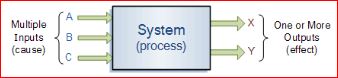
What is an input without an output?
When I looked at the schedule for input devices and output devices, I immediately thought of this question.
The Attiny45 is essentially is a micro-controller that has a program in its processor. It read signal input, then analysed it against the program and sends out a corresponding signal according to what the program had intended.
Input Devices
Sensors are usually refer as input devices. Sensors like phototransistor and photo diode that detects the amount of light, temperature sensors, pressure sensors, humidity sensors, fluid sensors, etc.
An input device reacts to changes in the environment around it and produced a electrical signal for processing to an electronic circuit. It is generally grouped into 2 categories; Active and Passive devices.
Acive input devices generated a voltage in response to changes around its environment. The following input devices do not need a separate power supply.
Examples are:
Microphone - generates a voltage when sound reaches it
Thermocouple - generates a voltage when its temperature rises
Solar cell - generates a voltage when light reaches its surface
Passive input devices have resistances which changes according to the environment around it. They need a separate power supply when in use.
Examples are:
Thermistor - resistance changes as temperature changes
LDR (light dependent resistor) - resistance decreases as the light intensity increases
Switch - has a very high resistance when open and almost no resistance when closed
Capacitor - during charging, the voltage across a capacitor increases with time
Design and Conceptualization
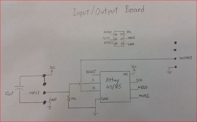
My practise is always to have a sketch of the circuit before doing anything else. In this assignment I'll be using the photo resistors (LDR) to sense light and send a signal to a pin of an Attiny45 chip as an input.
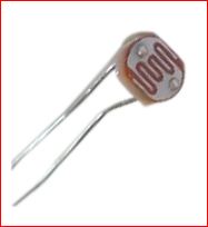
What is a photo resistor?
It is known as Light Dependent Resistor (LDR) whose resistance value is dependent on the light intensity increases. Meaning more light less resistance and less light more resistance. They are small, inexpensive, low-power, easy to use and highly durable.
The N5AC-10508 photo sensor and click link here for its datasheet.
The program for the Attiny45 chip will be a simple reading the signal from one of its pin programmed as an input then processed the signal and output a signal to drive a LED or a buzzer. The board I am going to design can have almost input devices connected to the PCB and the same goes to the output pins terminal
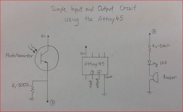
Simple input and output circuit sketch
Making the PCB
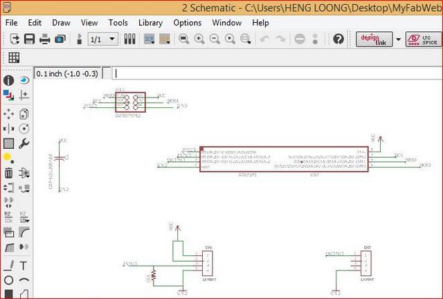
EagleCAD was used to design the circuit. The operating procedure will not be repeated here as it was described in Week 6.
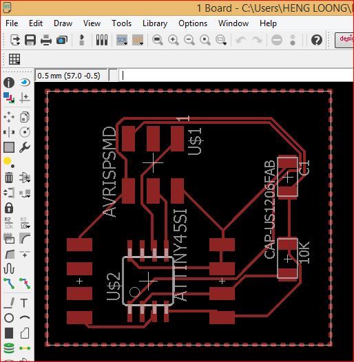
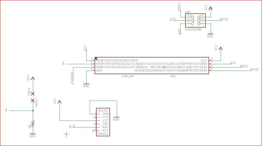
Below are the screen shots of the final input and output board. Schematic of the input and output circuit
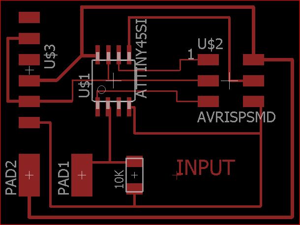
Layout of the input and output circuit components
The working files of schematic and board EagleCAD design can be downloaded here with a Right Click over them and "Save Link As".
Testing out
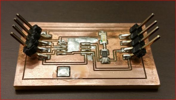
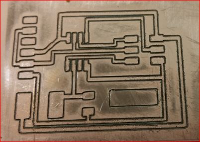
I did a continuity test on the PCB and found there are some paths were shorted together. Did another PCB routing by tweaking the depth of cut parameters slightly, meaning a slightly deeper cut. The results were worse than before, many paths were completely routed out causing open circuit between connectors. Routed another PCB with previous settings and did some rectifications and was able to clear the faults. After soldering components onto the pcb, noticed the paths near he pins of the attiny45 chip. Tried removing but the paths seems to have shorted together after verification with a multi meter. Had no choice but to remove the Attiny45. The pic below showed the condition of scorched terminal pins and amount of solder fused onto the copper surface.
Faulty input and output pcb
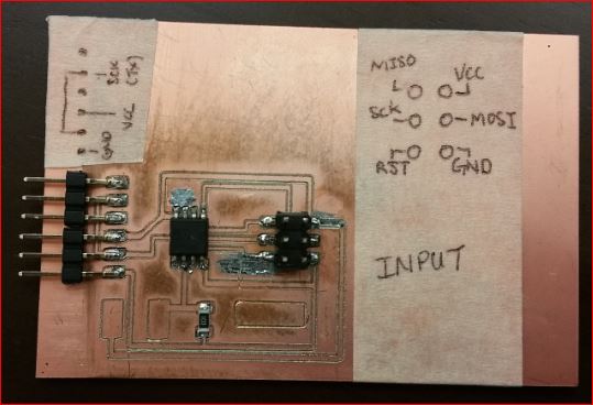
I used the 1x4 header instead of the ISP header because I am using the Arduino to function as the ISP. Therefore it is much more practical to use it this way as there will much plugging in and out of cables.
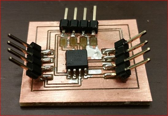
Did another round of PCB routing but I removed the capacitor and resistor to reduce fault variables, performed continuity test, soldered on the components and found a short between a pin terminal and to the adjacent copper paths. These pictures below made me understanded the meaning of the straws tat broke the camel back.
Pins broke and destoyed the copper surfaces
A short explanation of the program code
// if there is reading on pin 3 then it is HIGH:
if (sensorState == HIGH) {
// output pin 4 HIGH
digitalWrite (signalout, HIGH);
}
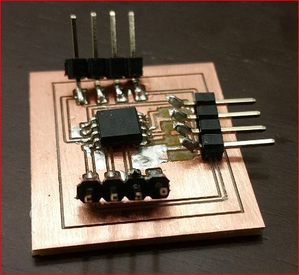
I was resolved to doing my own way to make it work. I first sketch out the circuit and shown below.
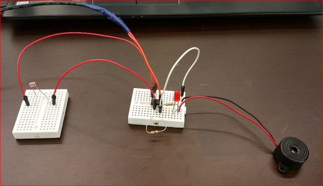
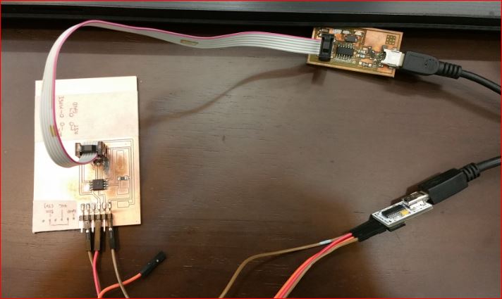
Followed up with the standard procedure of bootloader the Attiny45 chip and uploading the program into it. The final circuit would looked like as shown below.
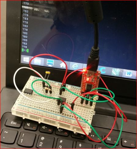
The video below showed the function of circuit.
The working files of Input and Output can be downloaded here with a Right Click over them and "Save Link As".
Making the Input PCB Board (Update)
I made a another effort to remake the PCB board for the input devices and this with a new design. The LDR will still be the input device and will display continuous read out to a serial monitor on the laptop.
The program was written in Arduino IDE and then the circuit was designed with EagleCAD before being milled out onto a PCB.